Hi,
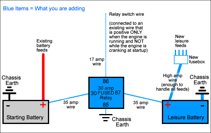
I've been thinking about how to charge my leisure battery for a while and have been trying to design a "smart" circuit to check the starter battery voltage and once this is past a set level (and therefore charged) to swap the alternator output to the leisure battery. I've seen lots of variants on the big relay connecting the two batteries in parallel and controlled by the alternator no charge circuit but I want to have two completely isolated systems (common ground though as I don't want to have to wire a negative through to everything off the leisure battery) so that I don't have to worry about the leisure battery draining the starter when they;re connected or voltage drops over diodes in isolating them. Saying this if my idea is useless I'll probably go with this as it seems to work, I'm just paranoid about not being able to start the car!
Anyhow after fiddling around with op-amp comparators and FET designs I came across an interesting bit of information, range rover classics (and possibly other models) have a voltage sensitive switch (VSS) inline with the rear demister to protect from over voltage. Could I use this to check the voltage of the starter and then control a relay switching between the two batteries with the alternator as the common wire. As the VSS is off above a set voltage (11V I think, will need to play with it and use a divider to compensate for needing a higher cut off) I'm thinking of having the starter as NO and the leisure as NC. This box http://www.power-store.com/view-item...d=1138&id=197&from merlin equipment seems to achieve what I'm after (although connecting both batteries in parallel again), though at £90 it's quite steep. The page might be a better explanation than my rambling!
Could someone electrically minded have a look at the attached circuit and let me know if it should work or if it's complete rubbish? Electronic design has always been a bit of a dark art to me and beyond very simple stuff I get easily confused so don't trust myself not to have designed a fire waiting to happen or a box that will sit there and do nothing!
Thanks
P.S. apologies for the black background, if it's hard to read will try to make a .doc version from the .eps file (which has a nice easy read black circuit on a white background but can't upload that)


Comment