

 Tweet
Tweet
i thought this was helpfull,
Diagnosis of KZ-TE . Troubleshooting. Schemes of connecting sensors and actuators to the engine control unit (ECU).
Repairs
The hands
Although rarely, yet sometimes there is a problem with the engine electronics failure 1KZ-TE . Which leads to the light bulb lighting up on the instrument panel, the CHECK ENGINE , and sometimes quite impossible to start the engine. Often it is something to do with a long downtime technology, soggy electronics, deterioration of contacts in a relay or connectors and wires.
The first resort to anything - check the fuses, then attempt to verify the vibration method of connectors, wires and relays in electronics box. It takes just check the voltage of the battery and its connections, the quality of the terminals, pay close attention to the wire and fixings to the body mass, the engine.
If the items listed above are normal, start diagnosis. Just make a reservation, documentation and diagrams precisely Haisu I do not, I use the circuit from under the instruction 1kZ-TE. Tying, respectively, if they will be different, it is insignificant, mainly - controlled glow plugs and, perhaps, a slightly different name of the relay and fuse, but the principle is the basis laid down the same signals and the same. Review your I prepared the material, which is available here: http://www.toyota-ace.ru/down/1kte.pdf
I'll start with the color-coded wires.
B (black) - black; L (blue) - Blue; R (red) - red; BR (brown) - brown; LG (light green) - c willow-green; V (violet) - Purple; G (green) - green; About ( orange ) - orange; the W ( Communities white ) - white; the GR ( gray ) - gray; the P ( pink ) - pink; the Y ( yellow ) - yellow.
When you specify a two-color combinations with a hyphen - in this case, the first light - color wires, the second indicator - color applied over the first strip (for example, the BR stands for black with a red stripe)
Because occur in practice, cases when the assembly constructors, or after repairs, torn connectors not bolted (soldered). In most cases, according to statistics, suffer from signal wiring in the place of installation, removal of a starter.
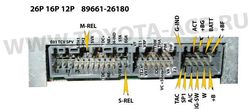
Now consider the "tying" of the engine 1KZ-TE , sensors, actuators, signal circuits, the power supply circuit of engine management (ECM).
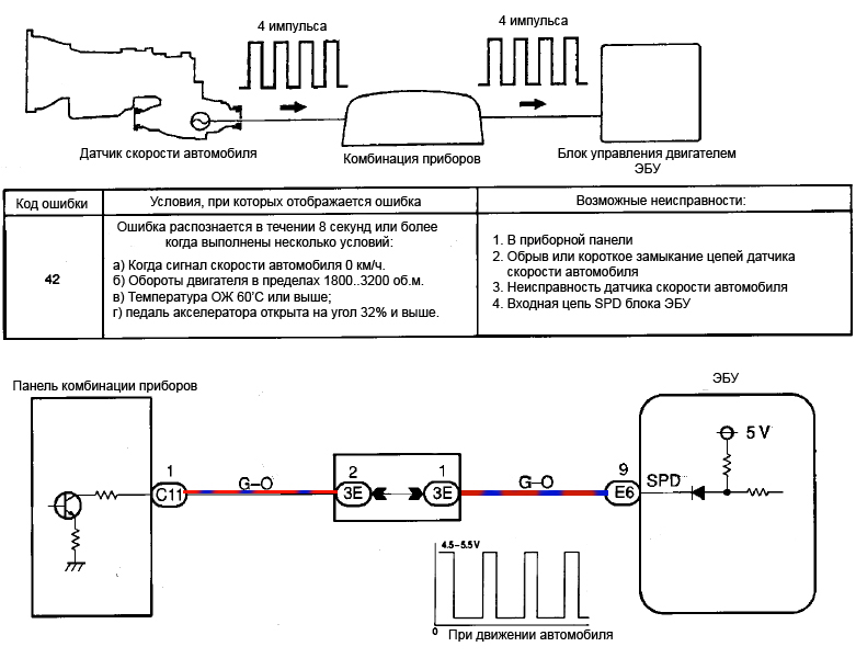
Connection to a computer the crankshaft position sensor (signal to the TDC ) and the engine speed sensor (in fact, the engine speed is calculated in the computer on the momentum NE sensor on the pump). The waveforms TDC and pulses the NE .
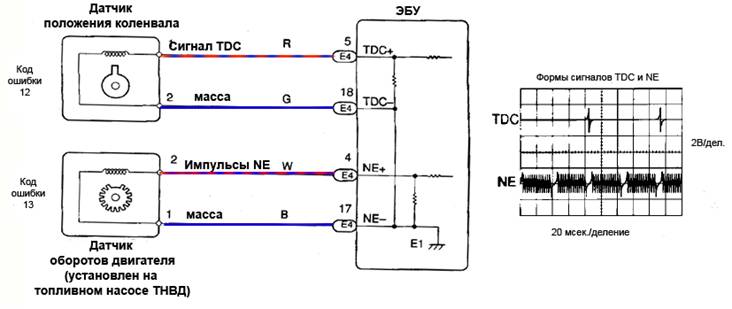
From the waveform in the figure we see the TDC unit impulse, this impulse is induced in the coil sensor crankshaft position during the passage of the TDC of the first cylinder and shows made one revolution of the crankshaft. NE pulses induced in the coil of the gauge of turns on the pump from the gear that has teeth pass. Incoming information is analyzed in the computer and synchronizes modes pump and motor.
Thus, in case of interruption or short-circuit wires to the sensor position of the crankshaft or a speed sensor, the sensor fault itself or open the input circuits in the computer unit, the engine control unit generates an error, respectively, 12 or 13.
Another one interesting case, we told forumchanin Artem, he had a problem with the connector on the sensor position of the crankshaft , wire rotted and had to rebuild the connector, when the works were accidentally reversed polarity switching of the sensor, resulting in a form of pulse signal TDC has changed a bit and shifted over time. What after the warm-up and on the move led to an error to fire the CHECK ENGINE . ECU unit was trying to adjust the injection time, acting on a valve the TCV , but apparently, adjust injection timing angle is not enough.
Sometimes erratic correction injection timing and to fire CHECK bulb causes bad tightening pulley pump, formed as a result of backlash and the key broke shponpaz course readings and sensor rotation of the injection rate became unpredictable. Correction of the injection angle to fail with an error code 14.
It happens - the plant is normal, but in the process sometimes there were failures, something klatsat, engine stalling, there was no error codes, it turned out - was slack wires from the crankshaft position sensor, insulation peretёrlas on rotating front propeller shaft to the ECU result, according incorrect data, trying to adjust the angle of the injection, the TCV solenoid chattering, responsible for the injection angle.
Another case was when the positive lead trying to apply something on sensors, not knowing what they do and what it may lead, in the end was a fatal RPM sensor error (error 13) at the operating sensor and wiring. On opening the computer found that burned mass conductor on the circuit board.
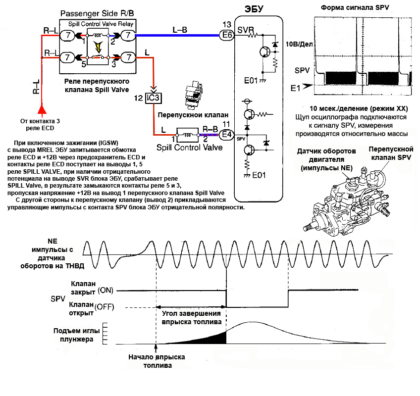
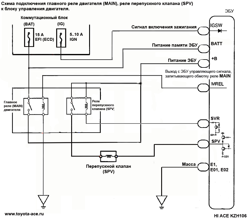
There are options to Break connectors Korotyaev engine weight dangling from sockets - conductors - so if you repeatedly knocks EFI fuse - look in the engine compartment and check the active electronic harness on the engine - especially pay attention to the actuators - electric vacuum valves ( STH1 / 2, E-VRV), devices with the reference voltage + 5V (PIM, TPS), as well as SPV chain, TCV.


Driving connection valve installation angle of injection at the fuel pump to the conclusion TCV ECU. Signal shape the TCV .
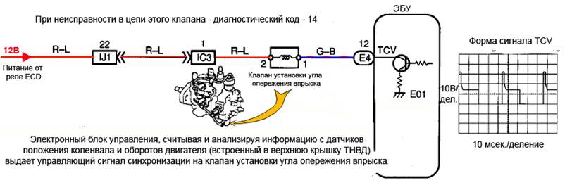
Resistance -solenoid valve installation angle of injection should be 10-14 ohms at an ambient temperature +20'C, measured by an ohmmeter to the sensor contacts, when disconnected from the computer unit connector. At discrepancy of the resistance of the solenoid - replace valve TCV. The same valve can be checked by submitting to him a short time (less than 30 seconds! ) Voltage of 12 volts (+12V on the output Bed and +, a lot of the withdrawal TCV solenoid ) must be clear audible clicks. But even they do not indicate that there is no jamming in the core, which reduces the range of automatic adjustment of the angle of injection and to fire CHECK lamp (14 error) in certain modes of engine operation. In this case, it helps the replacement or cleaning of the valve installation angle of injection. There are times when the carriage with rollers podzakusyvaet inside the pump housing due to scuffing or sticking fuel impurities, and does not give proper injection angle change during a working automation.
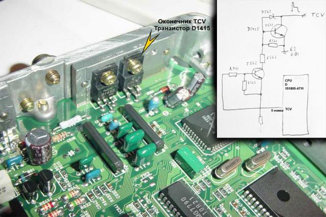
If TCV valve clicks and faulty wiring and transition connectors to the computer unit prozvanivatsya and normal, de-energizes the car by removing the positive terminal of the battery, take out the unit ECU and to understand it - look chain (track) TCV signal and its elements.
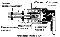
When current flows through the coil, the stator core by the electromagnetic field, retracts the movable rod, compressing the return spring to open the fuel passage connecting the high and low pressure chamber. The greater the value of the exposure control current to the coil TCV valve, the wider opens a passage between the chambers . Thus, the timer piston is moved to the right by adjusting the fuel injection timing.
Also noticed that in the case of pressure reduction in fuel injection pump housing in a pressure chamber upstream of the control rod TCV, fuel injection timing adjustment is small, so that the same will result in lighting up CHECK - 14. Reducing the pressure error can be caused by damage to or clogging of the fuel highway fuel zagelivaniem scored fuel filter and other obstacles to normal fuel passage (filters and filtriki on the pump set by the additional filter on the fuel line).
Temperature sensor connection diagram ( THW is ) coolant to the ECU. When checking sensor in accordance with the diagram, its resistance value at a specific temperature must meet the tolerance range.

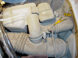
Temperature sensor connection diagram ( the TH A ) of air in the intake system to the computer. When checking sensor in accordance with the diagram, its resistance value at a specific temperature must meet the tolerance range.

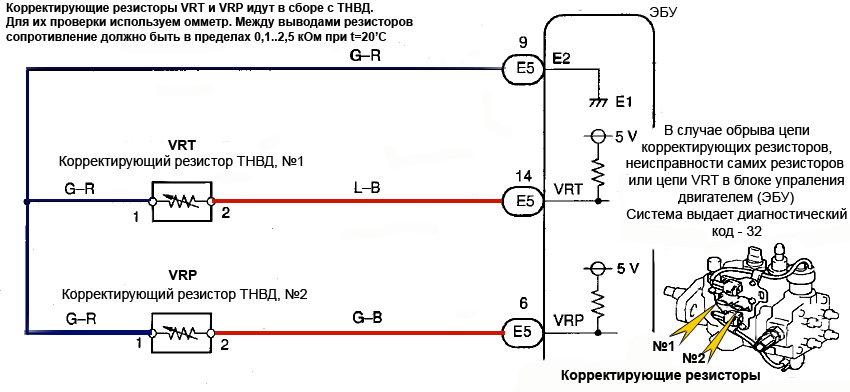
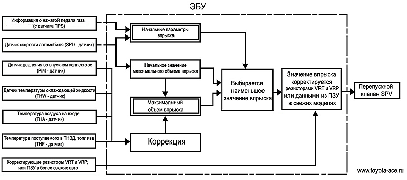
Connection to a computer unit correcting resistors. Corrective resistors typically do not change, and are supplied matched to this high-pressure fuel system.
Wiring the pressure sensor in the intake manifold to the computer unit. A plot of the voltage at the output signal PIM on the pressure in the intake manifold.
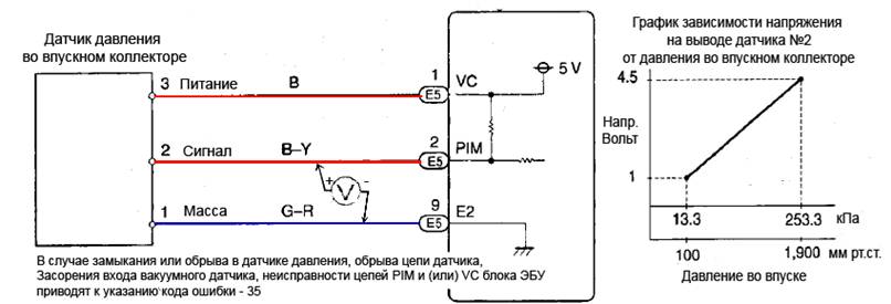
At pin 3 of pressure sensor in the intake should be about 4,5..5 voltage Volt. Measurements made with respect to weight, or one contact pressure sensor.
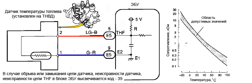
Driving fuel temperature sensor is connected, set the side of the cast-iron head pump to the ECU. When checking sensor in accordance with the diagram, its resistance value at a specific temperature must meet the tolerance range.
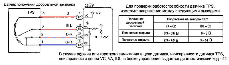
Wiring the throttle position sensor ( the TPS ) to the computer, as well as verification method.
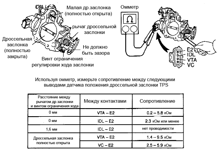
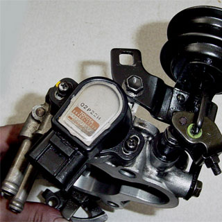
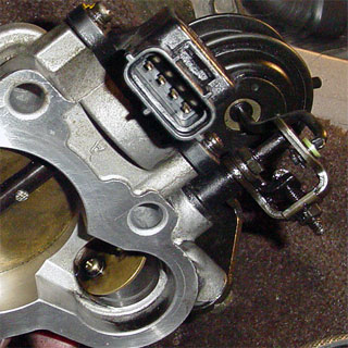
To learn how to remove the throttle for the prevention ofor test described here ...
Diagnosis of KZ-TE . Troubleshooting. Schemes of connecting sensors and actuators to the engine control unit (ECU).
Repairs
The hands
Although rarely, yet sometimes there is a problem with the engine electronics failure 1KZ-TE . Which leads to the light bulb lighting up on the instrument panel, the CHECK ENGINE , and sometimes quite impossible to start the engine. Often it is something to do with a long downtime technology, soggy electronics, deterioration of contacts in a relay or connectors and wires.
The first resort to anything - check the fuses, then attempt to verify the vibration method of connectors, wires and relays in electronics box. It takes just check the voltage of the battery and its connections, the quality of the terminals, pay close attention to the wire and fixings to the body mass, the engine.
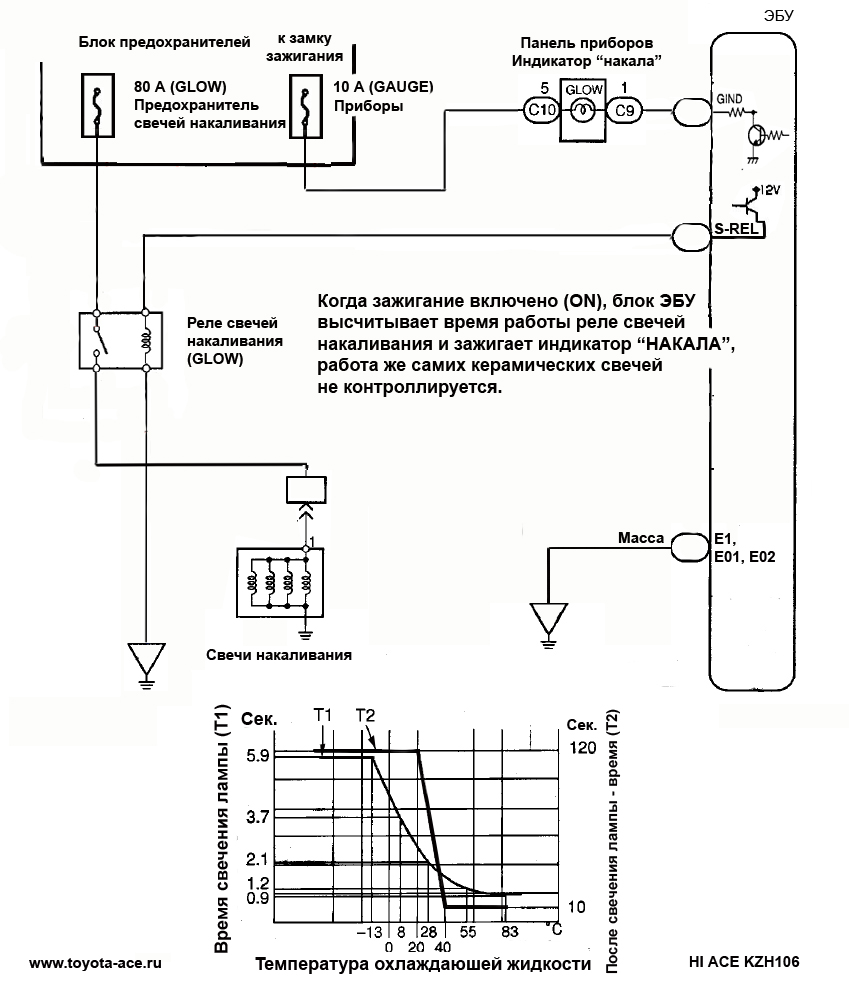
If the items listed above are normal, start diagnosis. Just make a reservation, documentation and diagrams precisely Haisu I do not, I use the circuit from under the instruction 1kZ-TE. Tying, respectively, if they will be different, it is insignificant, mainly - controlled glow plugs and, perhaps, a slightly different name of the relay and fuse, but the principle is the basis laid down the same signals and the same. Review your I prepared the material, which is available here: http://www.toyota-ace.ru/down/1kte.pdf
I'll start with the color-coded wires.
B (black) - black; L (blue) - Blue; R (red) - red; BR (brown) - brown; LG (light green) - c willow-green; V (violet) - Purple; G (green) - green; About ( orange ) - orange; the W ( Communities white ) - white; the GR ( gray ) - gray; the P ( pink ) - pink; the Y ( yellow ) - yellow.
When you specify a two-color combinations with a hyphen - in this case, the first light - color wires, the second indicator - color applied over the first strip (for example, the BR stands for black with a red stripe)
Because occur in practice, cases when the assembly constructors, or after repairs, torn connectors not bolted (soldered). In most cases, according to statistics, suffer from signal wiring in the place of installation, removal of a starter.
Now consider the "tying" of the engine 1KZ-TE , sensors, actuators, signal circuits, the power supply circuit of engine management (ECM).
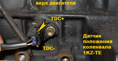
Connection to a computer the crankshaft position sensor (signal to the TDC ) and the engine speed sensor (in fact, the engine speed is calculated in the computer on the momentum NE sensor on the pump). The waveforms TDC and pulses the NE .
From the waveform in the figure we see the TDC unit impulse, this impulse is induced in the coil sensor crankshaft position during the passage of the TDC of the first cylinder and shows made one revolution of the crankshaft. NE pulses induced in the coil of the gauge of turns on the pump from the gear that has teeth pass. Incoming information is analyzed in the computer and synchronizes modes pump and motor.
Thus, in case of interruption or short-circuit wires to the sensor position of the crankshaft or a speed sensor, the sensor fault itself or open the input circuits in the computer unit, the engine control unit generates an error, respectively, 12 or 13.
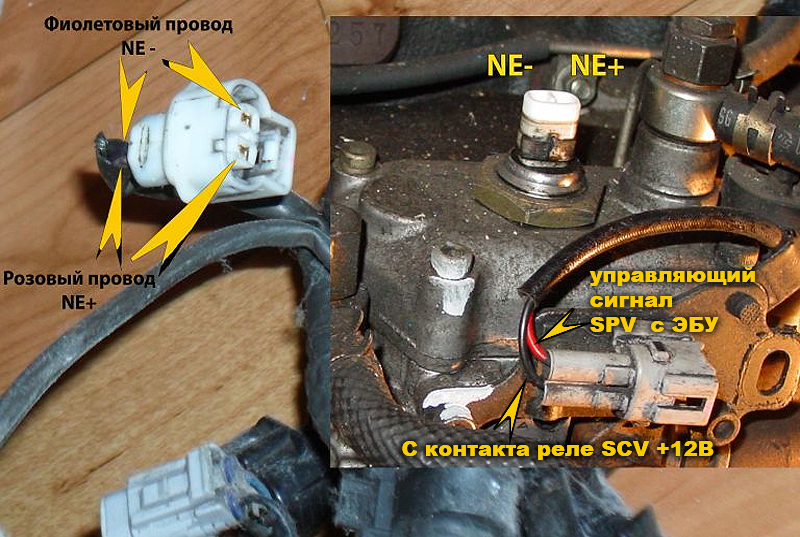
Another one interesting case, we told forumchanin Artem, he had a problem with the connector on the sensor position of the crankshaft , wire rotted and had to rebuild the connector, when the works were accidentally reversed polarity switching of the sensor, resulting in a form of pulse signal TDC has changed a bit and shifted over time. What after the warm-up and on the move led to an error to fire the CHECK ENGINE . ECU unit was trying to adjust the injection time, acting on a valve the TCV , but apparently, adjust injection timing angle is not enough.
Sometimes erratic correction injection timing and to fire CHECK bulb causes bad tightening pulley pump, formed as a result of backlash and the key broke shponpaz course readings and sensor rotation of the injection rate became unpredictable. Correction of the injection angle to fail with an error code 14.
It happens - the plant is normal, but in the process sometimes there were failures, something klatsat, engine stalling, there was no error codes, it turned out - was slack wires from the crankshaft position sensor, insulation peretёrlas on rotating front propeller shaft to the ECU result, according incorrect data, trying to adjust the angle of the injection, the TCV solenoid chattering, responsible for the injection angle.
Another case was when the positive lead trying to apply something on sensors, not knowing what they do and what it may lead, in the end was a fatal RPM sensor error (error 13) at the operating sensor and wiring. On opening the computer found that burned mass conductor on the circuit board.
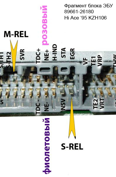
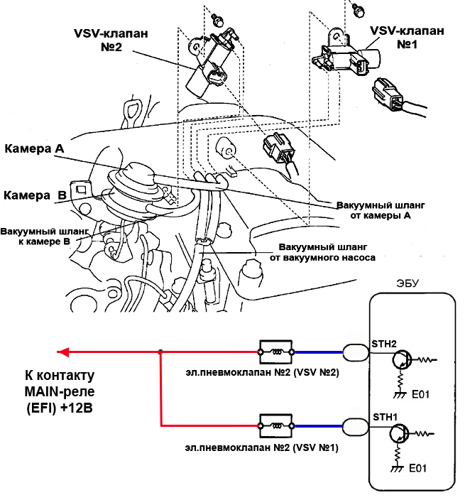
There are options to Break connectors Korotyaev engine weight dangling from sockets - conductors - so if you repeatedly knocks EFI fuse - look in the engine compartment and check the active electronic harness on the engine - especially pay attention to the actuators - electric vacuum valves ( STH1 / 2, E-VRV), devices with the reference voltage + 5V (PIM, TPS), as well as SPV chain, TCV.
Driving connection valve installation angle of injection at the fuel pump to the conclusion TCV ECU. Signal shape the TCV .
Resistance -solenoid valve installation angle of injection should be 10-14 ohms at an ambient temperature +20'C, measured by an ohmmeter to the sensor contacts, when disconnected from the computer unit connector. At discrepancy of the resistance of the solenoid - replace valve TCV. The same valve can be checked by submitting to him a short time (less than 30 seconds! ) Voltage of 12 volts (+12V on the output Bed and +, a lot of the withdrawal TCV solenoid ) must be clear audible clicks. But even they do not indicate that there is no jamming in the core, which reduces the range of automatic adjustment of the angle of injection and to fire CHECK lamp (14 error) in certain modes of engine operation. In this case, it helps the replacement or cleaning of the valve installation angle of injection. There are times when the carriage with rollers podzakusyvaet inside the pump housing due to scuffing or sticking fuel impurities, and does not give proper injection angle change during a working automation.
If TCV valve clicks and faulty wiring and transition connectors to the computer unit prozvanivatsya and normal, de-energizes the car by removing the positive terminal of the battery, take out the unit ECU and to understand it - look chain (track) TCV signal and its elements.
When current flows through the coil, the stator core by the electromagnetic field, retracts the movable rod, compressing the return spring to open the fuel passage connecting the high and low pressure chamber. The greater the value of the exposure control current to the coil TCV valve, the wider opens a passage between the chambers . Thus, the timer piston is moved to the right by adjusting the fuel injection timing.
Also noticed that in the case of pressure reduction in fuel injection pump housing in a pressure chamber upstream of the control rod TCV, fuel injection timing adjustment is small, so that the same will result in lighting up CHECK - 14. Reducing the pressure error can be caused by damage to or clogging of the fuel highway fuel zagelivaniem scored fuel filter and other obstacles to normal fuel passage (filters and filtriki on the pump set by the additional filter on the fuel line).
Temperature sensor connection diagram ( THW is ) coolant to the ECU. When checking sensor in accordance with the diagram, its resistance value at a specific temperature must meet the tolerance range.
Temperature sensor connection diagram ( the TH A ) of air in the intake system to the computer. When checking sensor in accordance with the diagram, its resistance value at a specific temperature must meet the tolerance range.
Connection to a computer unit correcting resistors. Corrective resistors typically do not change, and are supplied matched to this high-pressure fuel system.
Wiring the pressure sensor in the intake manifold to the computer unit. A plot of the voltage at the output signal PIM on the pressure in the intake manifold.
At pin 3 of pressure sensor in the intake should be about 4,5..5 voltage Volt. Measurements made with respect to weight, or one contact pressure sensor.
Driving fuel temperature sensor is connected, set the side of the cast-iron head pump to the ECU. When checking sensor in accordance with the diagram, its resistance value at a specific temperature must meet the tolerance range.
Wiring the throttle position sensor ( the TPS ) to the computer, as well as verification method.
To learn how to remove the throttle for the prevention ofor test described here ...


Comment