yobit eobot.com

Announcement

Collapse
No announcement yet.

How To: 2LTE Mechanical Conversion, Manual Glow Plugs, & Pump Reseal

Collapse
X
 
  • Filter
  • Time
  • Show
Clear All
new posts

  • How To: 2LTE Mechanical Conversion, Manual Glow Plugs, & Pump Reseal

    ***SEE A FEW POSTS DOWN, BROKE ARTICLE IN TWO.


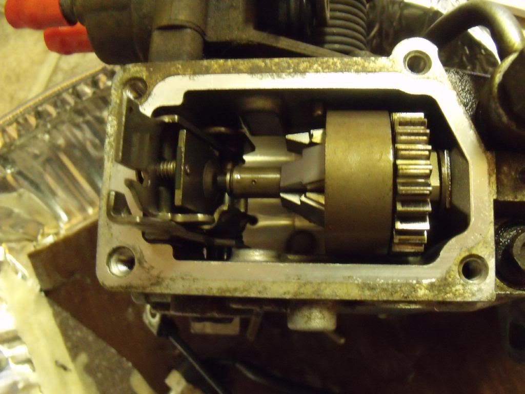
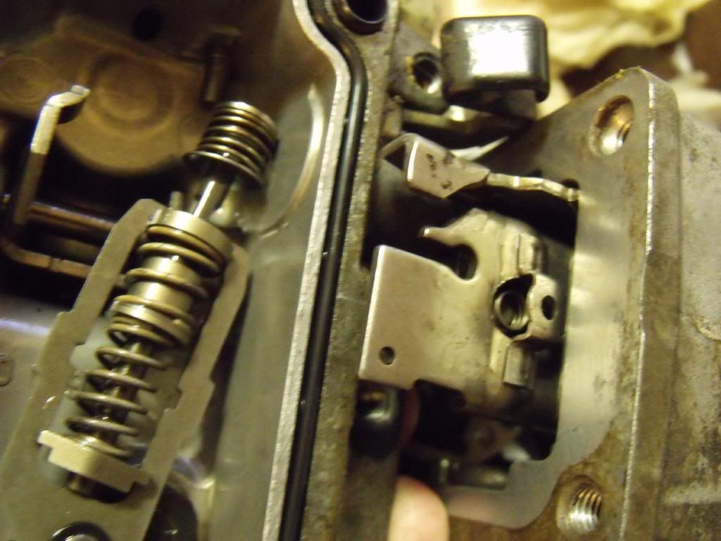
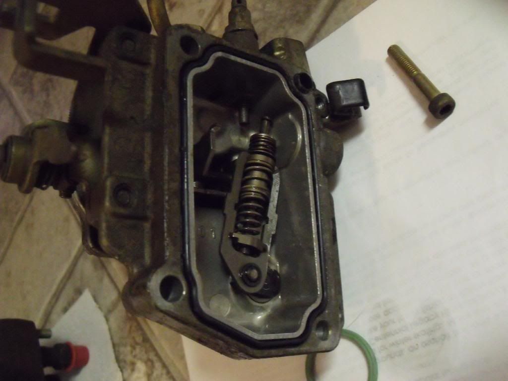
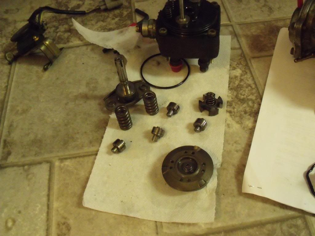
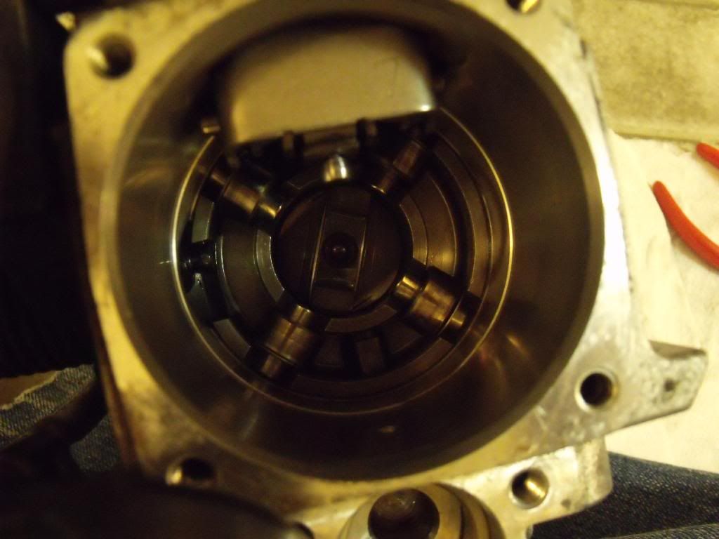
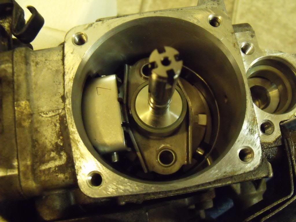
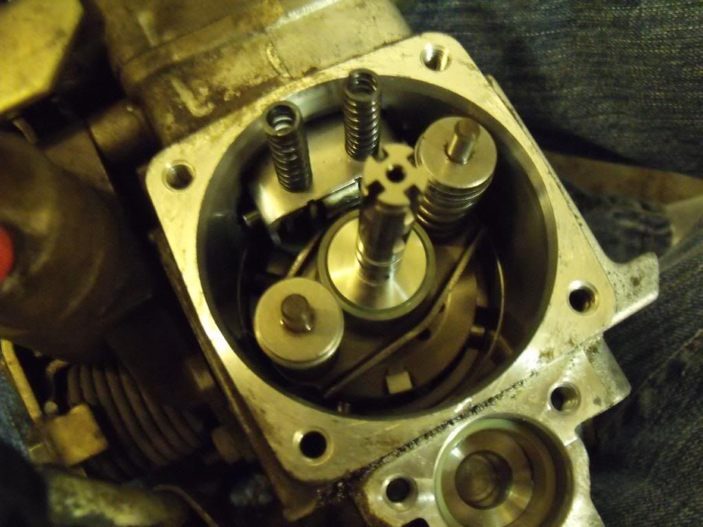
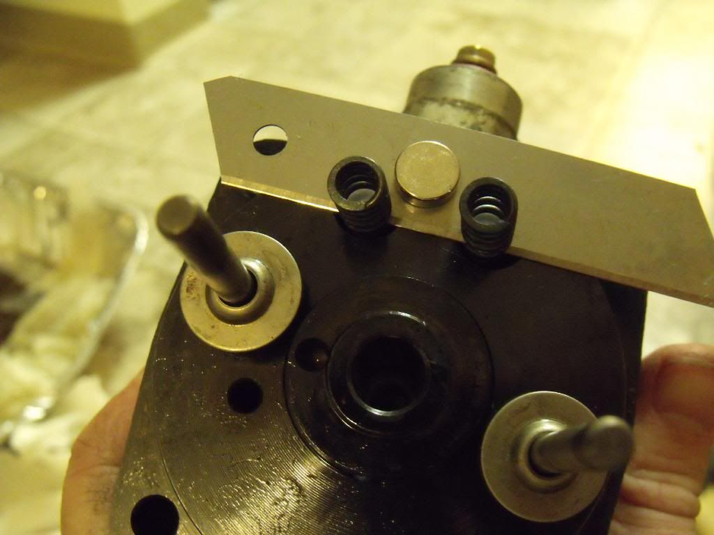
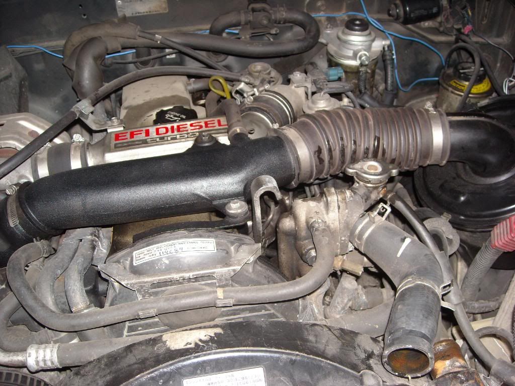
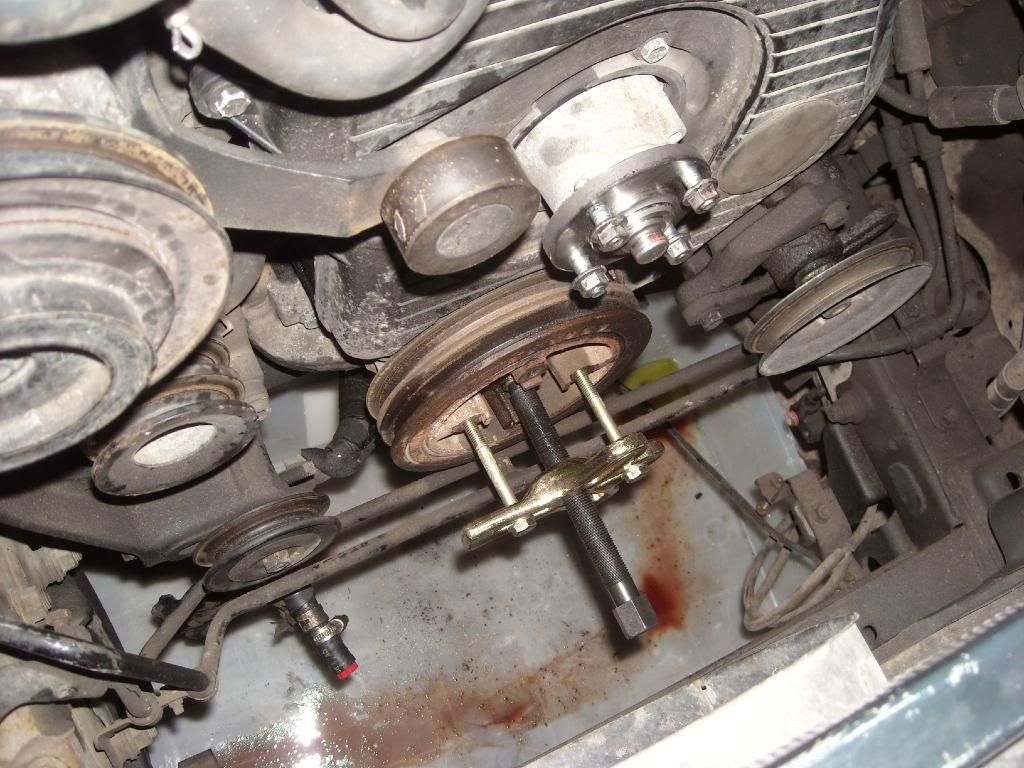
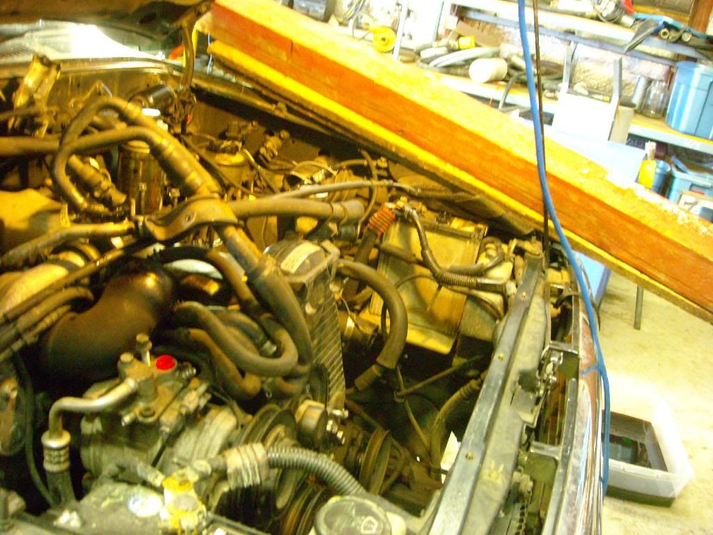
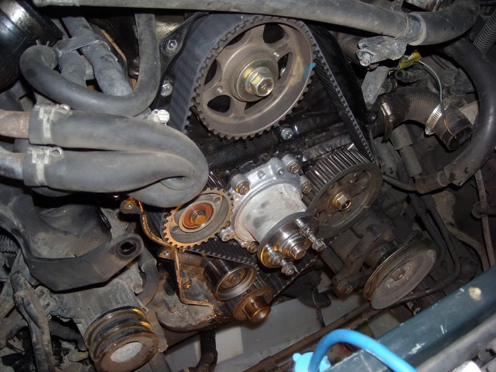
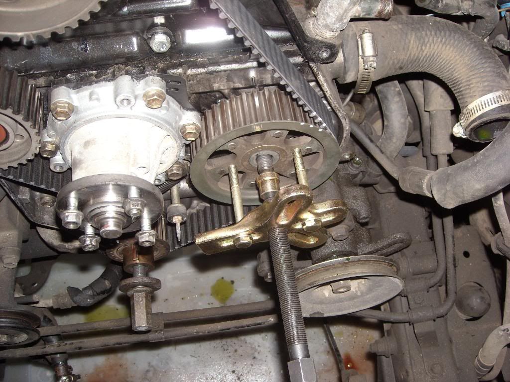
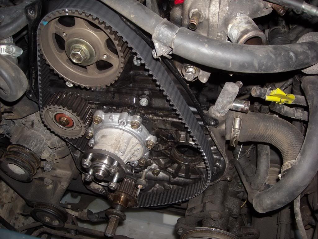
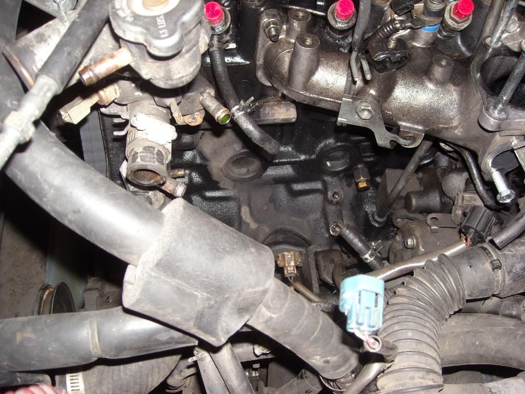
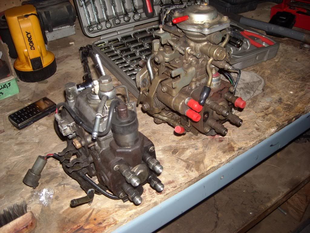
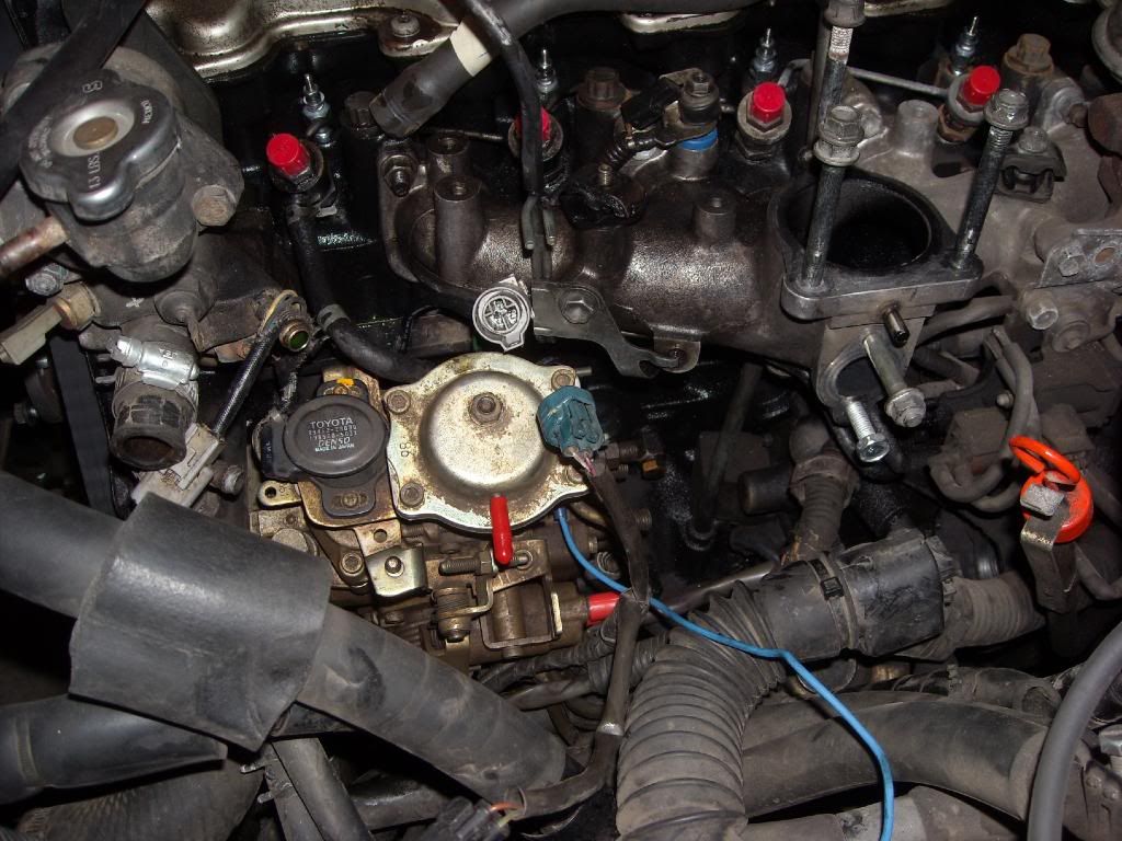
    The 10,000 character limit wouldn't let me post my thread here detailing my 2LTE to 2LT-II electronic to mechanical conversion in my '91 Surf. I also wired manual glow plug control, and an intake preheater that I touch on. I also resealed my injection pump, and detail the difficult steps of that. Hope it's helpful.

    http://www.toyotadiesel.com/forums/s...4829#post44829
    Last edited by Ardent; 16 May 2010, 01:58.

  • #2
    Wow! Fantastic write up.
    Unfortunately, the cost of dealer parts over here prohibits any modifications/conversions like that, it's usually cheaper just to buy another truck and part out the broken one.

    To put it another way, the costs for replacing a cracked cylinder head on the 2.4 is roughly the same as a 1UZ-FE conversion!

    Comment


    • #3
      Thanks, yes things are different up here, it's hard to get big parts. I'm looking to convert to a manual transmission, transfer case, and manual locking hubs. Any advice on where to look for the tranny and transfer case, and manual hubs that will work in place of my surf's electric locking hubs, would be greatly appreciated.

      ... and I'm just waiting for "should have disconnected the batteries". Yep, but got lazy, as I kept having to crank test things, and test wiring.

      Comment


      • #4
        Broken in two:

        Several months ago I went ahead and converted my formerly 2LTE 1991 Hilux Surf to a 2LT-II, or fully mechanical turbo. It's a conversion I'm extremely happy with, as if the engine turns over and there's 12V to the fuel cut solenoid, it's pumping fuel, and thus, running. No more sensors to fault, or ECU to decide not to let the fuel go, no more glow plug faults, etc. Electronic was a step backwards in my opinion, mechanical is perfect for diesels.

        First step, and a huge thanks to Lars for a veritable shopping list on this, is to gather the necessary parts:

        You need new throttle linkages, all available from Japan 4x4 for about $130:

        78100-35071 Link Assembly, Accelerator
        78104-22140 Rod Sub-assembly, accelerator connectine, no. 2
        78024-22100 Bracket Sub-assembly, Accelerator Control Cable.

        You also need new #1 and #2 cylinder injection lines, also available from Japan 4x4, they are cheap, under $100 for the pair, but one of the lines takes Toyota about 1-2 months to make. The old lines use the mounting point for the mechanical pump throttle linkage. Toyota part numbers:

        23701-54140
        23702-54120

        Then of course, you need a mechanical 2LT-II injection pump, hardest part to find, expect to pay about $500 for a good one. Mine was $400, and internally perfect. I did new seals on it before install, a good plan, but not an easy job. Bought my seal kit off ebay. I also bought NGK 11V glow plugs off ebay, as I wired manual 11V glow plug control. As well, I picked up an NGK diesel intake coil heater, meant for tractor applications, from the local industrial supply, cost me $40. I drilled and threaded my EGR block off plate for it, you need a 21/32" drill bit, and the M18-24 tap if I remember correctly, but don't quote me I'll check my tools later. Both the plugs and the preheat work great. Winter up here can be colder than -40º.

        Some of the things you have to do:

        I had to grind away part of the venturi/throttle butterfly housing, to make room for an injection line, as the routing changes. Easy and self-explanatory when you're mocking it up. I also chose to wire my throttle butterfly permanently open rather than go to the trouble of removing it, it is no longer used in the mechanical system.

        You will also need a dial indicator and adapter to time the new mechanical pump. If you're unfamiliar with the inner workings of these Bosch VE style pumps, there is a rotor inside the pump with four 'bumps' on it, basically think of them as cam lobes around the edge of a circular, rotating plate. These lobes stroke the pump, creating a fuel pulse, as they pass a given point in the pump and send fuel to their respective cylinders. A whole lot more goes on to advance the throttle, etc, but this is the basics. Since the pump is mechanically linked to the engine to keep time and inject, if you tilt the pump either way (either towards or away from the engine block), the location of the lobes on the rotating "plate" can move closer, or farther from the point where a pressure stroke's peak is made in relation to where the piston in the given firing cylinder is. That is, more, or less advance. Tilting the pump body (the rotating 'plate' inside with the lobes inside stays stationary, being held in place by its shaft's linkage to the timing belt) causes the injection point to be shifted to earlier in the piston stroke, or later. Tilting the pump body towards the block advances timing, tilting away, retards timing. You want to install the dial indicator in the pump's timing port, between the injection line nozzles, and tilt the pump in relation to the engine block until you record a stroke of 1mm/0.040". This measurement is easy to do, as it does not matter what the dial indicator reads, as long as you see a change of 1mm/0.040" vs. the bottom of the pump stroke when you have the engine with the No.1 Cylinder at Top Dead Centre. TDC is easy to find, as it's indicated by a timing mark on the camshaft pulley that you simply align with a corresponding mark on the block. There's slightly more to this, explained in the factory manual (which I didn't have, but I pieced together from online info), but this is the gist. You have to remove the starter to time the pump as you need the room for the dial indicator, not fun, but not the end of the world, pretty tight.

        Here's resealing the pump, and one trick I discovered. This is a tough, and tricky job if you do the main end/pump head seal. Keep everything CLEAN! I should have cleaned the pump externally very well first.

        Looking into the governor assembly, from the top of the pump. The governor linkage can be tricky to remove, you have to remove the top of the pump, the get your fingers or needlenose in the tiny crack and twist the governor linkage, allowing it to come out of its slot and let the top of the pump come off. It would be extremely difficult to perform with the pump in the vehicle.


        This is the linkage mentioned, and its corresponding slot. The slot is narrower than the diameter of the linkage shaft, and the shaft has flat spots milled on each side that allow it to drop into the slot if oriented properly, then twisting it 90º locks it in place. The reverse for removal. Tricky but not brutal.


        Top of the pump, with the new seal in place.


        Pump internals.


        Going back together, rollers in place. Be VERY careful with the rollers and washers, they like to drop into unseen parts of the pump if the pump's tilted from vertical. BAD news.


        Stacking in the components, be SURE to link the governor's connection ball into the plate at left in the picture. The ball, not unlike a hitch ball, could be left unconnected and the pump reassembled. This is VERY tricky this part.


        All stacked up and ready for the pump head to go on, HOWEVER, those 2 black little pressure springs are just standing there. BRUTALLY difficult to get the whole stack to stay put and press in the heavy pump head against the main pump spring pressure, AND ensure the governor's "ball" link stays in place. I found it impossible, so I had to rig a solution. I held the two little black springs, the most troublesome parts for me, to the pump head with a razor blade and a small earth magnet, slipping them of out the crack between the pump body and head when everything would stay in place (pic 2).

        Pic 1, springs "loose" and free standing. Impossible for me.


        Pic 2, razor blade and magnet retaining springs on pump head.


        The beginning, with the pump resealed. Time to remove the electronic pump, wire the manual glow plugs, and intake preheat.

        Comment


        • #5
          Part 2

          What you start with:


          You need to remove the following:

          -Transmission cooler, if installed

          -Air Conditioning system, if installed

          -Radiator

          -All Radiator hoses

          -Cooling Fan (remove four clutch nuts, can be tight)

          -Air Filter Housing, and Intake (steel part from turbo to intake manifold)

          -Venturi/Butterfly valve housing

          -Exhaust Gas Recirculation manifold (intake side)

          -Alternator mount (on my A/C Surf anyhow)

          -Crankshaft pulley (use harmonic balancer puller)

          -Timing belt cover

          -Timing belt

          -Injection pump pulley (use harmonic balancer puller)

          -All four injection lines, fuel lines to/from injection pump

          -Electronic Injection Pump, associated wiring harness


          I certainly haven't remembered everything.

          Pics, pulling the crankshaft pulley with the harmonic dampener puller.


          I used a breaker bar and a snipe on the deep socket for my crankshaft bolt, rest the snipe on the lumber and padding on the fender, then bumped the starter. Worked like a charm, but risky. You could shear teeth from your ring gear or starter pinion. Mine's an auto, so I couldn't just put it in gear and reef against it.


          Pulling the Injection Pump pulley with the harmonic balancer puller. Loosen pulley nut against the belt tension, this belt will be thrown away and replaced, no matter how new (mine was only 20,000kms old).


          It'll look like this now with all the above removed:


          Here's the electronic, and mechanical pumps side by side.


          Wire BOTH of the fuel cut solenoids on the Mechanical pump to a new lead, and give yourself some extra on the length of the new wire. With the starter motor removed, put the new pump in place:


          Then, use the OLD timing belt as a tensioner to hold the injection pump shaft in place while you torque on the nut holding the injection pump pulley on. This torquing against the belt will ruin the timing belt, so be SURE to replace it with a new one and don't use your new one for this. Time the pump as described above, then tighten it down and make a new timing pump mark on the block. This will help you determine if the pump's shifted, or if you should have to remove the pump again in the future you can then skip removing the starter and retiming it.

          Before I installed the new #1 and #2 injection lines, I primed the pump with the fuel filter hand pump after reconnecting fuel to the pump, and then cranked the engine with the starter until I had fuel coming out the pump nozzles to blast out any grime. Be CAREFUL with this, as the fuel coming out is so high pressure it will shoot through skin, and/or parts. I put a metal nut & bolt pan behind the pump head for this, and it lets you hear clearly from the driver's seat when the fuel starts coming out and hitting the pan. Then, install the injection lines, and tighten them at the pump, but leave them loose at the injectors. You'll crank the engine more to fill the lines with fuel. Again, be CAREFUL, and don't have anyone stand near the injector side of the vehicle. This is also a fire/explosion hazard, due to the misted fuel mixture you'll make out of your garage's airspace. Proceed at own risk. Standard stuff for a shop, and I'm going overboard on the warnings, but there is a risk some may not recognize.

          Once the injection lines are tightened down at the injectors, grind clearance for the new injection line routing into the venturi/butterfly valve housing, and reinstall the housing, being sure to permanently wire the butterfly open or remove the butterfly altogether. You'll need to make Exhaust Gas Recirculation (EGR) system block off plates as well, a simple task, as this will no longer be functional. Reinstall the Radiator, intake, air filter housing, and all other removed items and refill the coolant system with fresh coolant (I added water wetter as well, to give a little insurance on the head). I also installed a mechanical coolant temp sensor, that actually tells me the temperature in degrees. I bought a basic mechanical kit at a local auto supply store, and the 3/8" NPT brass bushing can be turned down with lathe or in a drill chuck with a file and threaded into a blocked off port in the coolant system just under than rad cap.

          The manual glow plugs, I wired through a winch solenoid and 4 gauge copper welding cable to a push button in the cab, which makes sure they can't be flicked on and left that way accidentally. The 4 gauge cable ensures 11V makes it to the 11V plugs, and handles the amps. I LOVE the manual glow control. This was what scrambled my ECU however, and prompted my conversion, so I would be careful on 2LTE's, as it's likely you're bypassing the computer isolate during start as the plug timing is no longer in accordance with the ECU's isolation timing in the start sequence, and the power draw can cause real issues. Like a fried ECU... I believe that's what I did to mine anyhow.

          While you're in there, you can replace your water pump, front main and camshaft oil seals, glow plugs, general belts, valve cover seal, etc etc. I took advantage of having the truck that far apart to do a lot, as it's not something you want to do often. Hope this is helpful to some! I received so much support in researching the conversion I promised to write it up after.

          Thanks again!

          Comment

          Working...
          X