
 Tweet
Tweet
Hi All...
Ive recently got a 1990 surf 2.4TD manual...i bought it not working...a bit of an unfinished project from the previous owner...the head cracked and the guy fitted (well started to!) a complete recon engine...
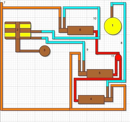
anywho...none o the vacuum pipes were conected...ive found a load of info about where they conect from previous posts and think most of them are now in the right place...the only one im struggling to find a home for is the pipe that comes from the alternator....its in to the steel pipe across with the turbo pipe..then.???...
i got a lot of info from the line digram that has been posted before..however i just cant find where this bit should conect to!...
that aside...its running now altho its lacking power above 2000rpm...im hoping it could be down to this pipe?....
Cheers all..and i must congratulate you on a great forum
Ta
Sparkz
Ive recently got a 1990 surf 2.4TD manual...i bought it not working...a bit of an unfinished project from the previous owner...the head cracked and the guy fitted (well started to!) a complete recon engine...
anywho...none o the vacuum pipes were conected...ive found a load of info about where they conect from previous posts and think most of them are now in the right place...the only one im struggling to find a home for is the pipe that comes from the alternator....its in to the steel pipe across with the turbo pipe..then.???...
i got a lot of info from the line digram that has been posted before..however i just cant find where this bit should conect to!...
that aside...its running now altho its lacking power above 2000rpm...im hoping it could be down to this pipe?....
Cheers all..and i must congratulate you on a great forum
Ta
Sparkz


Comment